Showing posts with label torx T25 screws. Show all posts

Monday, July 28, 2014

Mirror mirror


Hello to all!

This time I'll write a step by step instruction regarding on how to upgrade your side mirrors to the 2007+ model, the ones with integrated side markers, or blinkers.

If you have read the previous post, you know I have bought a pair of rear "jewel" taillights. I told you that I have also bought a pair of 2007+ side mirrors with integrated blinkers and courtesy lights.
I was really happy to have found them especially because they were already in the same color as my current mirrors.
So, first things first. Disassemble my mirrors and put the new ones in place. The procedure is very easy and straightforward. You start by opening the door and removing 2 plastic trims using a bone tool, or as I do it, with a credit card :) since I don't have a bone tool. For this first piece I always start from the bottom and go up.
Behind it you will find 2 Torx 25 mm screws. One is at the bottom.
And the other is on the upper part of this assembly.
The second plastic trim is the one that is above the door cover in the corner.
Behind it you will find a 13mm bolt that holds the mirror attached to the door.
Do not unscrew this bolt just now, first you have to continue to disassemble the door cover. It is still held in place by 8 plastic retainers like the ones in the picture below:
The way I remove them (although it's not the only way) is press the center piece with the tip of the same Torx screwdriver I used on the screws before. This way, I prevent breaking them and assure their reusability. After the retainers are off, all you have to do is lift gently the door cover  and then pull it gently towards you. Now disconnect the door handle release wire pictured below;
 and the 3 connectors you see in the picture.
Now you can put the cover (panel) aside and proceed to unscrew the aforementioned 13mm screw that holds the mirror in place. And this is how it looks after I have removed the mirror.
For the reassembly I followed the same steps only backwards. And below is the new mirror in it's place.
And another shot from the front.
The final shot with both mirrors installed:

But this was not the end of this project. The mirrors worked fine, the courtesy light, electric heating and adjusting were working as they should have. This is because the new mirror had an exact connector as the old one.
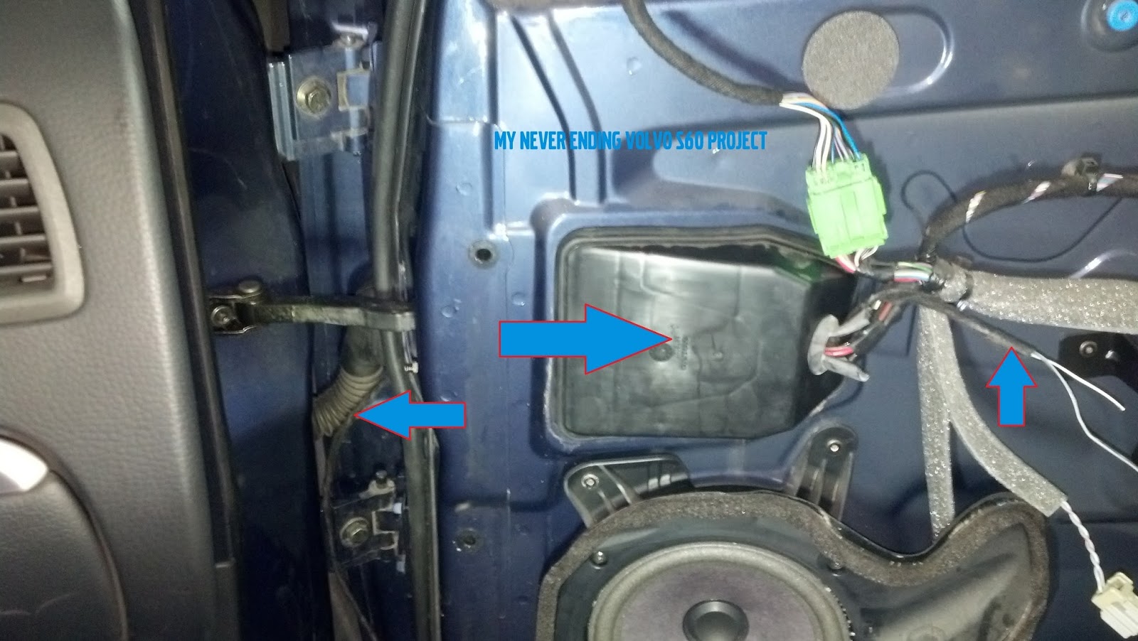
However, the incorporated turn signals did not work, because, there was no wire connecting the new mirror to the turn signal relay. So the next step was to connect them. So I had a look on how to pass the wire from the mirror, through the door and pull it all the way in the front next to the original side marker. At first I didn't find a way, but after a few minutes I found a way so I wouldn't have to drill a hole through the door. This is what I did: You can see in the picture below there is an arrow pointing to a large plastic cover and anoter arrow pointing to my new wires.
First, I took out that cover. It is held by to inner clips, you just have to pull it gently and it will come off easily. So I passed my cable through the seal that is depicted in the picture below. That rubber hose that you see in the picture is filled with other cables. There is no point in passing your cable through it because, at the other end (near the door inner edge) it has a white connector that has two 10mm screws that hold the connector and hose to the chassis. So I unscrewed the screws and pulled the connector.... 
so that I would pass my wire under the rubber hose
Now, I decided I will discard one of the bolts from this connector and pass my wire through the new hole that I created. The screw is not molded into the plastic of the connector. Using a 6mm star bit I managed to unscrew it from the connector.
Next, I passed the cable through the hole in the door that I obtained by removing the connector's screw.
Now, I placed the connector back in it's place, and you can see my wires passing through the door in the new hole.
And the bolt is back on the screw and the connector is back in it's place safe and sound.
This stage, the wire is safely placed in the door, and passing through it freely under the plastic hose that you can see between the door and the fender.
The last step of the wiring was to "fish" the wire through the hole in the fender where the side marker is located.
Now, I connected the white-black wire to the brown wire and the gray-black wire to the green wire.
And completed the circuit on the mirror's end connecting the white-black wire to the black wire and the gray-black wire to the mirror's blue-black wire.
Of course, there are other ways to make all this work. This was the method I chose, basically because I did not have suitable metal pins for the mirror's green connector. So this is a temporary solution until I find this type of pins. The important thing is that both mirrors work and the blinkers work.

Well, that's it. Hope you like the result and hope you found this useful. If you decide to do this project, and you need help, use the comment section below, or use my Facebook page and I will try to help you.

Safe journeys everyone!


Sunday, May 11, 2014

Volvo S60 CCM disassembly


Hello again!

Today it's another DIY post about the disassembly of the CCM or Climate Control Module. I must note that my car is a 2002 model but this tutorial is similar to all model years.
So, let's begin. First off, you will need a bone tool, or, if you are like me and have none, use a credit card or gift card to unclip the pen holder under the CCM. There are 2 plastic clips that hold this piece of trim. I recommend, if you have manual transmission to put your car in second or 4th gear so that you have a little more space to maneuver.
After you have successfully removed this trim, you will find 4 T25 Torx screws. You will need to unscrew the ones that I have marked in the photo. The other 2 hold the gear lever trim in place
You are almost done. Now, you can pull the CCM using your hands like so. The CCM is still held in place by 2 clips that are attached to the HU. Using two fingers, each on opposite sides as a lever, you can lift and pull the CCM out.  

After you pull it out you will see 2 green pin connectors (already removed in the picture but marked with the green arrows) and another connector for the cigarette lighter (that one comes out pretty hard, you may want to use a flathead screwdriver as a lever to remove it).
Hope you'll find this information useful! 
Safe journeys, and see you next time!


Friday, May 9, 2014

Volvo S60 front bumper disassembly


Hello!
It's been a while. The people that follow this blog, know that a few months back I decided to close it. After some time thinking about how much work I invested and seeing that what I do here actually helps some people, I decided to bring the blog back

So, let's get cracking.
Today I decided to write about the steps necessary to take the front bumper off your car. As you may already know, I have changed my headlights (new post soon) so in order to remove them I had to take the front bumper off.

This procedure is easy. You start by taking off the bumper moldings. You can use a bone tool or your bare fingers if you are careful enough not to scratch the paint.

If you have a '00 - '04 front bumper model like mine, all you need is to pry the left and right moulding. The center one and even the license plate can remain on your bumper. However be careful not to pull too hard so you won't break the little clips holding the molding to to bumper.

Next step is removing the 6 plastic clips from under the hood. They can be removed easily by pressing them with a screwdriver. After you are done with whatever work you had to do with your bumper you can reuse them.
Next you have 1 torx T25 screw on both sides of the car under the wheel arch that need to be unscrewed . As you unscrew it make sure you push on it, this way it will push against a locking mechanism that is attached to the bracket that holds the bumper. 
Lastly there are two 10mm screws that need to be unscrewed and you are almost done. One is on the right hand side...
And the other on the left hand side
After all this unscrewing and pressing, it's time to take it off. I suggest you put some cloths or something soft under the front bumper before proceeding. The last part requires 2 persons because it is easier to slide the bumper off the brackets this way. I am not saying it can not be done by a single person, I'm just saying it is more difficult that way. 
After you have detached the bumper from the car, let it rest on the cloths, but be sure that you disconnect the fog lights (if equipped). The fog lights are very easy to take out of their housing. 
Done. Make sure to store the bumper out of your way and place it in as much of a natural position as possible to avoid warps or chips of the paint.
End result

It's good to be back! Safe journeys everyone! Don't forget to comment in the section below if you have any questions or ideas. I would love to read them! Hope this helped.


Sunday, March 31, 2013

Volvo S60 DIM disassembly

A big hi to all my readers! When I created this blog, I had one thing in mind, that being sharing with all of you my ideas of possible upgrades to my Volvo S60, and also to help my readers when they begin their projects. Each time I upgrade something from now on, I will also try to post a tutorial. That being said, I now open the DIY Tutorials section, with my first tutorial regarding Volvo S60s DIM or Data Information Module (the instrument cluster) disassembly.
My first step when I start a project involving the electrical equipment is always to take of the leads to my battery. However, considering that the Volvo S60 has the battery in the trunk, and under a plastic shield which is rather hard to take out without taking out the spare wheel, I disconnect the leads under the hood.
You can find them under a small plastic door attached to the fuses box. Unscrew the bolt and you are good to go.
Secondly, go in the car and place the steering column in the most outward and downward position. If you have small hands and are confident that you will not scratch your cars trim you can skip this step, but bear in mind that the work space for this project is pretty small.
Now we start taking out the outer plastic rim surrounding the DIM. You need a firm but soft hand. All you need to do is to pull outward and up the rim using both your hands witch you place on the upper side of this plastic rim.
After you did this, your dashboard should look like in the picture above. Now, the bottom part of the plastic rim is taken out in a similar fashion. You place your hands right above the steering column and place your fingers in the small opening just above it. With a firm upward pull, you should have now disconnected the plastic rim. 
Final note about the plastic rim. It will still be attached with 3 evenly distributed plastic clips against the small plastic cover of the steering wheel (picture below)
Pull them out gently, and your done. Now, your dashboard should look like this. The DIM is fixated with 4 torx T25 screws. Yes, there is a lot of dust in there too, mainly because, I never taken the DIM out before and the car is 10 years old, and secondly, I'm sorry to say there is a lot of dust in Romania.
 2 T25 screws on the right.
  and another 2 T25 screws on the left.
All you need to do is to unscrew them. Careful not to drop the screws. You're almost done. Next, pull gently the DIM out and place it face down against the steering wheel like in the picture below.
Find the green DIM connector located approximately in the middle of the clusters back panel. You can already see it in the picture above, and the next pictures below.
 Now disconnect it by pressing the small protuberance on it and pulling it out.
You have now successfully disconnected your DIM.

Part 2 of the project is how to take apart the DIM.
The DIM is composed of 3 parts that are attached together by plastic clips. There is the electronics part which is located in the white plastic casing, the black plastic casing which is the part where all the kph and revs, etc are painted upon and the final part is the lens. Using a Flathead screwdriver you can gently separate them. As you can see in the picture below, there are 3 black clips and 4 transparent clips on the bottom which have to be undone.
 On the upper side of the DIM there are another 3 clips that hold the white electronics part. Undo them gently. Now you have access to the electronics module.
 lifting the lens and black trim of the instrument cluster.
 The lens is attached to the black plastic part by 5 transparent clips. Undo them gently, and be careful about the center one, I broke a sweat trying to remove it
Well, that's about it. Now your DIM is disassembled. To reassemble it, press all the parts carefully back, and follow all the steps back. Don't forget to reattach the green connector and the leads to the battery and your all done.
I wish to thank my brother-in-law for helping me (you can check his games site if you like) and, of course my fiancee for cleaning up inside the car where all the dust was (check her cosmetics website or her blog)

Well, I hope everything was clear and helpful. If you encounter problems, contact me or write me a comment. Also if you like my work, keep reading and let me in your ideas by writing a comment below.

Till next time, safe journeys!