Hello everybody!
I was thinking about trying to unite even more the Volvo community and feature everyone on my blog. All you have to do is to post a picture (the one you wish to post on my blog) of your car and yourself on Instagram with the #mys60projectfeatured and your car's nickname. If you like, you can also add me on Instagram: http://instagram.com/andikoo82
I'll start with my picture of my VOLVO S60, nicknamed The Blue Anti Tank Gun

Thursday, December 26, 2013
Sunday, December 22, 2013
Seeing double
Hello people!


This year, just before Christmas, I decided I wanted to give me a present. So, I started by buying an used 2005 Volvo S60 rear bumper with all the brackets. So I searched the net, and in the end, I found one in Hungary at a salvage shop. After speaking several times with the owners of the shop, I went ahead and bought it, along with a pair of 2005 Volvo S60 tail lights, based on the pictures they sent me by mail:


However, they proved to be very deceitful and highly unprofessional. I ended up getting this piece of junk and no tail lights after nearly a month of waiting:
The sad truth: it wasn't even the same color as the one depicted in the photos they sent me


This was the "icing on the cake": broken plastic trim

After looking at it, I almost decided to drop the entire project, the blog and everything. After almost a month of being constantly on the road, I managed to get the car to a specialist shop, where my muffler was cut down. A few days later, my new tips arrived, so we started by changing the rear bumper. We did this for 2 reasons. First, my obsession of updating the looks of the car to the newer P2 Volvo S60. Second, it was much easier to cut the hole in that spoiler for the right hand exhaust tip.
Original bumper off

The conversion of the rear bumper is very easy if you have the side brackets. They are needed to ensure a perfect fit. Even with the '02 brackets installed you can mount the newer bumper, but the fitting will be a little off.
I'll cover the rear bumper conversion in another post in the DIY section.
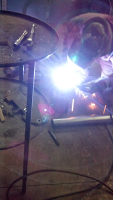
What followed was a lot of welding.

The split for the dual exhaust

The split installed

Measuring the clearance of the new left exhaust tip

Final position of the exhaust tip

Left side tacked into position

The rear bumper was then cut to match the left side, and the exhaust pipe was tacked also into position.
All it took was to finish welding all the parts together and presto:
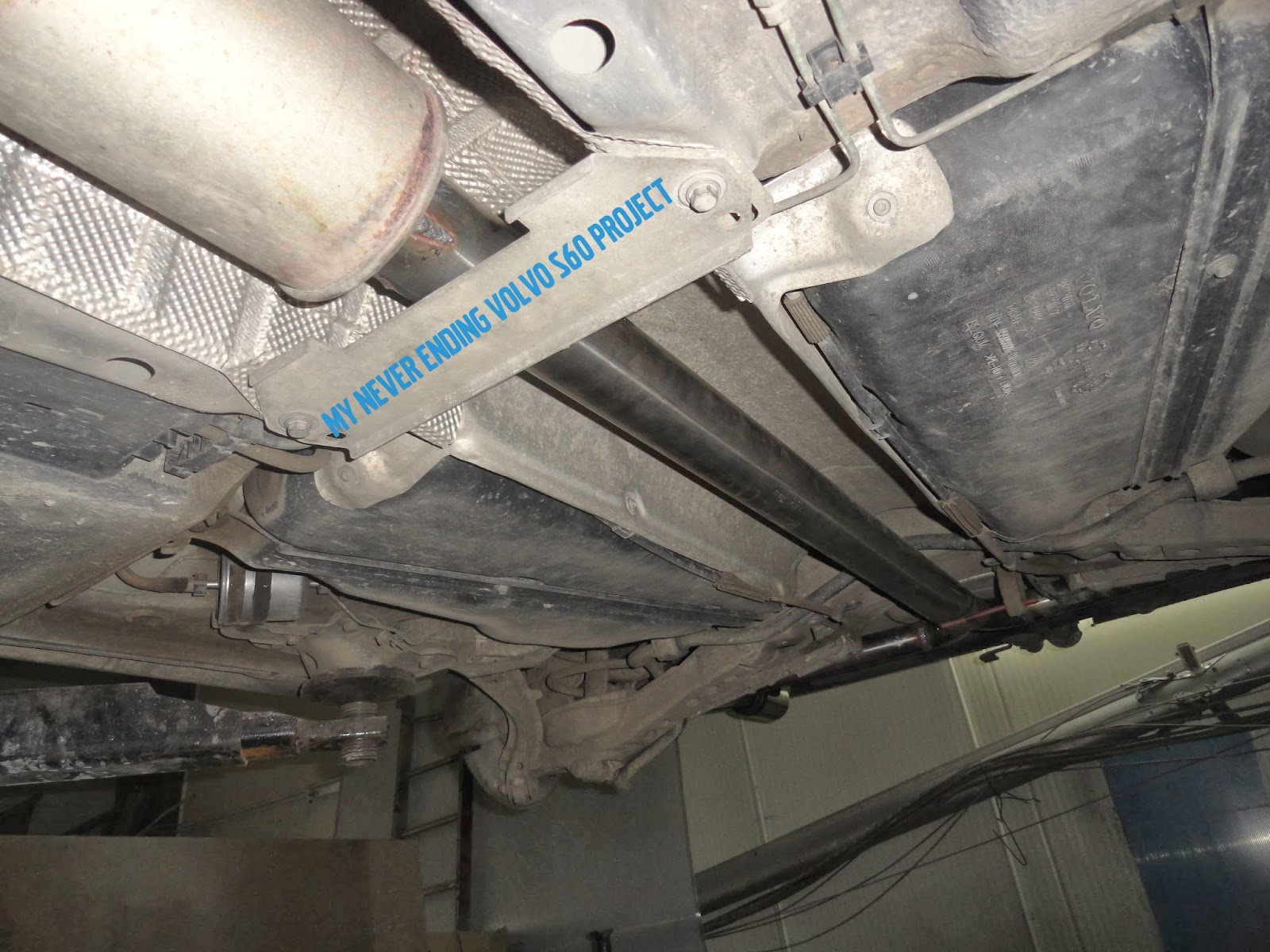


The main advantage of this system over the commercial ones like I mentioned in my wish list is that the exhaust coming out of the dual pipes is equal or symmetrical

In January I will take the rear bumper back to the specialist shop for repairs and paint and I will keep you posted. Till then, one last picture:

I will end this post wishing you all, a Merry Blessed Christmas and A Brand New Year full with wishes that will come true!
Safe journeys everyone!
UPDATE: 25.01.2014
Hello all!
I managed to fix and paint the bumper at a specialist shop. Now, the rear end transformation is almost complete. All I need now is to rebadge the car with the new spread VOLVO lettering and a pair of 2005+ rear lights.
Leaving the shop
At home, in the garage
Safe journeys everyone!
Friday, October 25, 2013
The key switch
Hi all!
Today I will post about what I changed yesterday. For years I've been yearning to get my hands on a Switchblade style key fob for my Volvo. So I finally decided to buy a complete case with an uncut blade from ebay.It was cheap, about 30 $. Normally I would have made another post with the unboxing of the key, but this time, I didn't really like the seller so I will not do such a post and will not recommend him because the delivery took more than a month. The key is very nice and functional, but the wait was terrible.
So let's get down to business:


 After all this, I placed the transponder in the new casing where I showed you, reassembled the key, and voila: new switchblade key fob conversion completed.

Today I will post about what I changed yesterday. For years I've been yearning to get my hands on a Switchblade style key fob for my Volvo. So I finally decided to buy a complete case with an uncut blade from ebay.It was cheap, about 30 $. Normally I would have made another post with the unboxing of the key, but this time, I didn't really like the seller so I will not do such a post and will not recommend him because the delivery took more than a month. The key is very nice and functional, but the wait was terrible.
So let's get down to business:
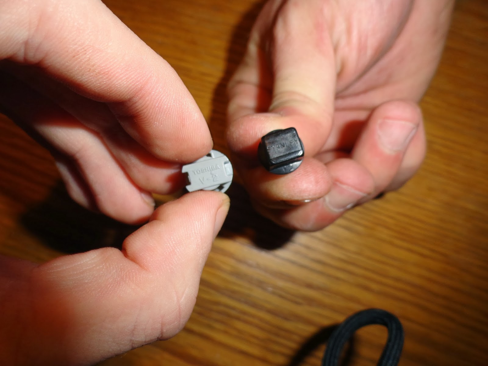
Here's the new uncut key next to my old key. Notice to the left there is a small screw that came with the new key.

So what I did first was to disassemble the new key completely and take the uncut key out. I bought this type of case which is not OEM, it is a replica, because it can be dismantled completely and therefore I can use all the electronic parts from my old fob in it, therefore, after all the process is done, I have a working key, without having the need to go to the dealer and program it.
If you choose to go the same way I did, when you try to take out the key, pry apart the 2 plastic parts holding the key gently, because there is a spring inside.
I got the key cut at a specialised store (I was surprised how little it was, about 3-4$)
My old key again, with the blade (now cut) and the top part of the key fob

And a quick reassembly of the top part holding the cut key (just to test how difficult it is)

This key case I bought didn't come with any electronics. So it was up to me to insert my electronics from my key. First I started with the easy task of switching the motherboard. It is very easy to do. You only have one 8T torx screw that holds your remote in place. Unscrew, and separate gently.
Here you can see the remote electronic board moved it the new remote.

I also transferred the metallic contact for the battery from my old remote, the new one didn't had one but has a place where it fits perfectly.

Now the next challenge: To get the transponder out of my original key and into the new one. Note: without the transponder chip, your new key will open your car and turn on the ignition but the engine will not start and you will get a fault code.
Here is where the transponder chip will fit.

Now... where can it be? WARNING (Slasher movie pics following)

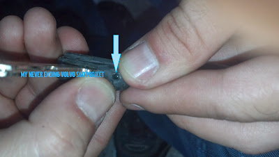
For this part I had the aid of my brother in law. So, where to cut first? I decided to cut on the left side of the key when holding the key with the manufacturer stamp up. Basically, on one side of my key is stamped Valeo (manufacturer) and on the other is Made in (somewhere). And after a few slices, in the other parts of the key, because I couldn't find any references as to where the chip is located, I started going deeper in the original place where I started cutting.
So I passed the soft plastic layer, then a hard plastic, and going deeper I found another layer of soft plastic.
Blue arrow soft plastic, green arrow hard plastic

That moment I knew we found it. So we started cutting the top side of the plastic to find a hole to get it out and sure enough, after a few layers of plastic here it was:

I also took another picture with flash on so that you can see better the glass case of the chip

Here is the transponder chip located. Picture taken after I removed the soft plastic cover using only my finger nails so not to accidentally destroy the transponder

Using a wooden toothpick I pried the transponder chip out noting the position.

Final result:

The upper part of the new key fob (the one holding the key, transponder, spring and the silver button) will need to be glued shut so that it will not accidentally dismantle when you turn the key in the ignition.
Hope you liked what you've read. If you consider doing this yourself and find yourself in trouble, or if you need advice, or if you just want to share opinions, please use the comment section below.
.
Friday, September 27, 2013
New V O L V O trunk badge from ebay seller braydonmotorcompanyltd
A big hello to all my readers!
I've been putting off this new unboxing post for a while now because I was busy writing the LED conversion post.
So long story short, I got the new model VOLVO badge for the trunk. I highly recommend this seller, delivery was quite fast, the package arrived in Romania from the U.K in only 3 days.
This is what I got in the mail:


Inside the envelope was the badge in original unopened packaging

Here is another shot using my "vintage" red chair as a contrast and support

The badge cost was £26.99, shipping was £5.00 and the total was £31.99 taxes included.
Installation will be covered in a new DIY post where I'll show you also how to debadge your car, or at least, my method.
Till then, happy journeys everyone!
Wednesday, September 25, 2013
The long road to Full LED conversion. (will be continued)
Hello guys and gals!
Foremost I must say, this post is going to be a little different. Since there are a lot of bulbs inside the car, and I am a very pretentious guy, I will leave this post open, and continue to add pictures and stories as I progress with the conversion.
If you would like a recap to where I am currently with the conversion (well, before this post), you can recheck this post.
So, as you may recall, I wrote in the last post the types of LEDs I acquired. Therefore I had 2 jobs to do: first change the H1 bulbs from the fog lights and then, changing the bulbs in the DIM with the T5 LEDs that were waiting for me to start already.
Alright, the fog lamps were almost easy to do. Of course, it is much easier if you have access to a lift like I did.
Here is a pic of the original H1 bulb

And another pic of the replacement LED

As you can see the original bulb gives a bit more light. If the weather will require, I will go back to original, however the LEDs give out a pretty good amount of light during the night. So I'll wait for the foggy season to start to decide if I'll keep them or not.
Here is the finished look. Please note that I haven't turned the Xenon short beam on, it's only the daylights that are on and the fog lights.

On a funny note, after me and my brother in law finished fiddling with the lights, my car's battery was dead. Luckily he had a spare battery laying around so we hooked it to my car's to jump start it. What followed was a short test drive just "to test the recently cleaned MAF" and not to charge the dead battery :)) ;).
Second job was the DIM partial conversion. You'll see soon why I say partial and not total:
First step was to take the DIM out of the car. You can follow this post to see how. Afterwards, I made a small sketch of all the bulbs I had in the DIM:

Using this sketch, I decided I wanted to switch to LEDs the following bulbs: numbers 1,2,5,6,7,8,9,10,11. I didn't wanted to change the color of the side markers or any other engine failure markers. But after counting the LEDs I had and realising I had 11 pieces, I decided I'll do the side markers as well as a test. So numbers 3 and 4 were added to the list.
There are 3 types of bulbs in your DIM if you have the same model year I have. If you have a newer Volvo S60, you may already have LEDs soldered in your DIM.
Here is the black socket one

Here is the grey socket one

Here is the black and greys
The side markers are of a different kind, they have a blue socket but the bulbs in those sockets are similar in size to the grey ones.
Here we have the bulb removed from the black socket

... and LED installed in it's place

All the sockets with the bulbs come out of the DIM by rotating the counter clockwise gently.
So, the bulbs in the black sockets came out relatively easy, the bulbs from the grey and blue sockets however, were a pain. You can not possibly grab them properly, the bulb has a much more smaller glass area for me or my brother in law to grab and pull. And since the only member of my family with smaller hands, my wife, was sick with the flu and in bed, I had to resort to a trickery. I used a long pin (that was originally used during my wedding to hold the flowers in the bride's bouquet).
Here is the pin I used to take out the bulbs out of the grey and blue sockets.

I used this pin to gently push out of the socket the small bulbs. I can not show you the process, but I can tell you that the bulb has a small, tiny curve right above the socket which I used to pull the pin head into and then I used the pin as a miniature crowbar or lever if you will.
All LEDs were now in place, time to reassemble everything and see the result:


Before I close this post (for now), I must remind you that LEDs have polarity, meaning that If when you light up the DIM, they don't work, you must note on your sketch which one is defective, take it out, rotate it 180 degrees, then put it back. If they won't lit, they must be broken. You can see in my pictures that the LED that lights up the odometer is not working. After I did the procedure described above it worked.
Conclusions: I like the color. It's much more refreshing than the color I had. However I don't like that now, the light in the DIM is not evenly distributed. You can see that some spots are more lighted up than others...
Stay tuned. After I did all this, I ordered other LED which I hope will cure the uneven light distribution. I will soon post new pictures with the new LED and will show you which one I kept and the ones I changed.
Till next time, safe and happy journeys everyone!
UPDATE: SEPTEMBER 26th
Hi again! So I finally got home and was able to pick up my new LEDs I have ordered. As you have read above, I wasn't quite pleased with the uneven light distribution given by the SMD T5 LEDs. I liked the color but not the result. So I ordered this babies:
White T5 triple led.

So I decided to switch all the black T5s from the black sockets (see above) with this type of LEDs.
Here you can see the SMD T5 LED in the socket I just removed from the DIM and next is this new type of LED.

However this new type of LED is a bit trickier to insert into the DIM because of it's form. They will enter the DIM eventually, you just have to be patient and insert them at an angle.

I decided not to change the grey socket ones because of the smaller than that of the black ones DIM opening, and besides, the light distribution of the grey ones was perfect already.
So, I'll let you decide if the end result was worth the effort. I think it's absolutely beautiful!


So many more buttons left to do. Soon I'll start on the CCM and HU.


You can cleary see in the middle picture below that the light was a lot more powerful around certain spots like the 100km mark or the 6000 rpm using the T5 SMD LEDs. But in the third picture, after I replaced the SMD from the black sockets with the triple LEDs everything is now even.

I would like to thank again my brother in law for helping me and let's not forget my lovely wife for her continuous support!
UPDATE: DECEMBER 24th
So, I ordered some new SMD LEDs for my light switch and CCM.
I started with the light switch

My method of dismantling the switch doesn't require tools. I simply open the side panel of the dashboard, stick my hand there...

...and push the switch from the inside out.

Lighting the switch are 3 T4 Neowedge bulbs.There is also a green connector which can be easily pulled off

You need a flathead screwdriver to turn this type of bulbs counterclockwise to be able to take them out.

After reinserting the T4 LED, I put everything back together.

And a night picture. Very disappointed of the color. They are crystal whites. Was expecting a white blueish one just like my DIM dials. Will probably change this LEDs also.

Next was the CCM (Climate Control Module)

I will make another post on how to disassemble the CCM
On the CCM we have 6 T4 bulbs, 2 green connectors and one white connector for the cigarette lighter
The CCM has other bulbs or LEDs that are in the housing, but I didn't get to them (being so cold in the car).
Will convert all the bulbs to blueish white LED later, for now I upgraded just the T4s

Here is the end result. You can see how much brighter the LEDs are compared to the old bulbs that still light the DSTC and other buttons.

SMALL UPDATE: FEBRUARY 12th
I don't know if it's just my car or this is a common fault in Volvo S60s, but I've been plagued by the a repeating burning of the side rear lights. So, after a few burned bulbs, I decided to switch them to LEDs. This was a no brainer, since those particular lights do not give a burned light warning in the dash, we are able to use any kind of LED type (SMD or normal) providing they are a replacement for the R5W bulb.
Installation is so easy and it only takes about 2 minutes, this is why, if you're plagued by the same "disease" i recommend this switch to everybody, even those who don't want a full LED conversion.
The faulty bulb in its socket
The same faulty bulb. As you can see it's a R5W
The culprit next to it's replacement. I chose a SMD white LED.
And the SMD LED back in the socket. Light output is satisfactory.
Night shot
Conclusion: time required minimal ( it took longer to take this pictures :)) ) . Economy wise exceptional considering the cost of the SMD LED equivalent to about 5 halogen bulbs but life time of the SMD will exceed the lifetime of more than 8-10 consecutive halogens.
Hope you like the results! Leave a comment if you do, or why not if you don't! Thanks! See you soon!
Subscribe to:
Comments (Atom)